| Home |
| About MWRA |
| Water System |
| Sewer System |
| Harbor and Bay |
| School Program |
| Doing Business with MWRA |
| Contact MWRA |
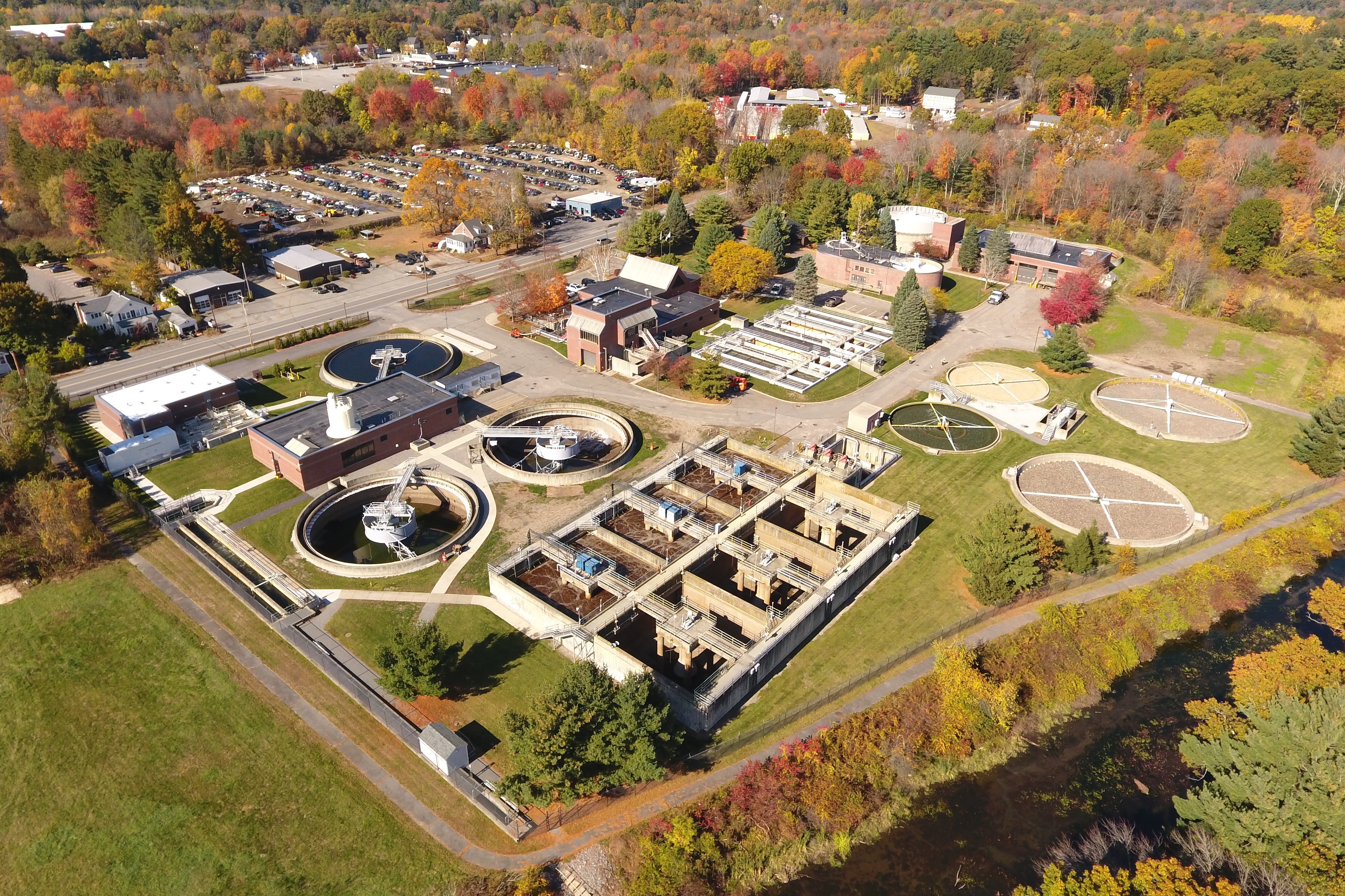
The Clinton Wastewater Treatment Plant
Massachusetts Water Resources Authority
MORE INFORMATION |
|
The Clinton Wastewater Treatment Plant provides advanced sewage treatment services to the town of Clinton and the Lancaster Sewer District. MWRA assumed formal operational responsibility for the Clinton plant in 1987.
Since then, MWRA has designed and constructed new primary, secondary, and advanced treatment facilities that incorporate rehabilitated portions of the existing plant with new construction.
The new facilities, designed to meet all current and projected NPDES discharge standards, were completed in 1992. A Phosphorus Reduction Facility was completed in 2017, designed to meet discharge standards in the NPDES permit issued in 2017.
CLINTON WTP'S FACILITIES
The plant provides secondary treatment using an activated sludge process in combination with advanced nutrient removal, disinfection and dechlorination.
The major facilities include a headworks, primary settling tanks, digesters, sludge processing, trickling filters, aeration tanks, secondary tanks, and a phosphorus reduction facility. The plant discharges its effluent into the South Nashua River in accordance with the discharge limits of the facility's NPDES permit. Residual materials are pressed and transported to an MWRA owned landfill for disposal. Staff also perform regular monitoring of the landfill site.
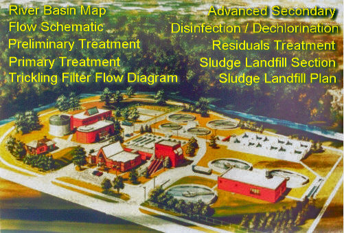
CLINTON WASTEWATER TREATMENT PLANT DETAILS
Click the text in the image below for more details about the treatment plant and its processes.
Clinton Wastewater Treatment Plant Statistics
| Influent Receiving Structures | |
| 5 Influent lift Pumps | Design Capacity (MGD) Avg - 3.01 MGD, Max - 12 MGD |
| 2 Parshall Flumes (Lancaster and Clinton) | Throat Dimensions (Clinton Only): Width: 18" Depth: 36" to 45" |
| Grit and Screenings Removal | |
| 1 Bar Rack | Type: Manually cleaned 1 3/4" clear opening |
| 1 Mechanical Bar Screen | Channel width: 30" Channel depth: 64" Incline angle 10O Clear opening: 3/4" Drive motor, (hp/rpm): 2/1800 |
| 2 Aerated Grit Chambers | Dimensions (each): |
| 2 Grit Screw Collectors | Type: Helical Screw Length: 18' |
| Primary Treatment Process | |
| 4 Primary Clarifiers | Type: Rectangular, chain and flight -Average flow, 2.03 MGD: 3.2 (2 units operating) -Peak hour flow, 12 MGD: 1.1 (4 units operating) |
| Collector Mechanisms | Type: Straight line, longitudinal and cross collectors, chain and flight 4 Cross-collectors (one per basin) 8 long-collectors (two per basin) |
| Sludge Collector Drive | Type: Helical spiral bevel gear w/overload clutches and shear pins
Drive Motor, hp/rpm: 0.5/1800 |
| 8 Scum Troughs | Type: Manually operated, rotating troughs
Though width, ft/ section: 12' |
| Chain and flights | Type: Polyester reinforced fiberglass
Long flight speed/spacing: 2 fpm /10' |
| Trickling Filters | |
| 2 Tricking Filters (existing) | Type: High-rate roughing filter Size, (dia x depth) ft: 60' x 5' Rotary Distributors: Organic Loading Rate. lb BOD5 / day /1000 cu ft: |
| 2 Trickling Filters (new) | Type: High-rate roughing filter Size, (dia., x depth) ft: 80' x 5' |
| Media / Material: 3" to 1.5" crushed stone | Depth, ft: 5' Volume,: 30,150 cu ft (ea) |
| Rotary Distributors | Type: 4 arm, primary and secondary Min./max. flow, MGD (ea): 1.008 / 5.04 |
| Organic Loading Rate, lb BOD5/day/1000 cu ft: | Average/max.: 65 / 130 |
| Advanced Secondary Treatment | |
| 5 Intermediate Lift Pumps | Two submersible pumps and three screw pumps Design capacity (MGD):- Slow speed, (24 rpm): 3.0024 MGD - Fast speed, (48 rpm): 6.0048 MGD |
| 6 Aeration Tanks | Basin dimensions, each: 50'(L)x 50'(W)x 17'(D) Detention time, hrs: |
| 3 Clariflocculators | Type: Circular, Rapid sludge return
Inside diameter: 80.25' |
Nitrification at the Clinton Treatment Plant is accomplished in the activated sludge tanks. Nitrogen removal takes place in the activated sludge process at the aeration basins. Nitrogen removal is desirable to reduce nutrient levels to the receiving water thereby inhibiting algae growth and reducing oxygen demand on the river. Nitrification is accomplished by a biological process, which utilized nitrogen as an energy source. Proper conditions must be maintained such as dissolved oxygen supply and pH control to promote microorganism growth. |
|
| Phosphorous removal at the Clinton Treatment Plant is accomplished in a Phosphorus Reduction Facility completed in 2017. Ferric chloride and a coagulation polymer are added after the final clarifiers to precipitate phosphates into a filterable solid. Disc filters in the Phosphorus Reduction Facility capture the coagulated material for further sludge processing. Phosphorus removal at the Clinton plant limits the potential for excessive algae growth in the Nashua River due to high nutrient availability. | |
| Dechlorination takes place at the over flow cascade of the chlorine contact chamber. Sodium bisulfite is sprayed by injectors into the effluent stream to remove chlorine residual before going to the receiving stream. | |
| Disinfection | |
| 2 Hypochlorite Contact Tanks | Dimensions, ft: 100'(L)x 6'(W)x 14'(D) Total volume: 125,665 gals. Contact time, minutes, (both tanks): -Average (2.03 MGD): 89 mins. -Maximum 24-hrs (8.2 mgd): 22 mins. -Peak hour (12 MGD): 22 mins. -Average usage: 70 gpd of 15% hypochlorite sol. |
| Dechlorination | |
| 1 Sodium Bisulfite Tank | Capacity: 1200 gals. containing 38% Sodium Bisulfite Sol. |
| 1 Bisulfite Diffuser Assembly | Dechlorination process occurs at the diffuser assembly located immediately below the discharge from the hypochlorite contact chambers. Average Usage: 50 gpd of 38% Sodium Bisulfite Sol. |
| Outfall | |
| 1 Parshall Flume | Throat dimensions, in.: -Width: 18" -Depth: 36" to 45" |
| 1 Step Cascade | To increase effluent D.O. level before discharging into South Branch of Nashua River |
| Residuals Treatment Process | |
| 2 Gravity Thickeners | Design hydraulic loading:200 to 500 gpd/sf |
| 2 Anaerobic Digesters | Type: Single-stage, Floating and Fixed Covers, gas mixed. Tank size (Fixed Unit), ft: - Diameter: 40' - Max. water Depth: 28' Tank Size (Floating Unit), ft: - Diameter: 40' - Max. water Depth: 28' - Min. water Depth: 26.5' Max. Capacity, gal (combined): 526,100 gals |
| 1 Anaerobic Sludge Holding Tank | Type: Sludge and gas holding, secondary digester, floating cover, gas mixed. Tank size, ft: Diameter: 60' Max. water depth: 25.33' Min. water depth: 20.33' Max. capacity , gal: 474,410 gals |
| 2 Belt Filter Presses | Type: Pressure filtration, dewatering Manufacturer/model: Ashbrook-Simon-Hartley/ Klampress, size III Type 85. |